PRACTICAL MIDDLEBROOK METHOD FOR OPEN LOOP GAIN SIMULATION IN OSCILLATOR CIRCUITS
(2014-02-02)
Preface
In the past days I was doing some experiments with a 443 kHz oscillator for a 455 to 12 kHz DRM converter. Prior to circuit building I made several LTspice and QUCS simulations just to be safe about oscillation. Simulation is an useful thing before using the soldering iron blindly. I wanted to learn more about oscillation.
An oscillator is an amplifier plus a feedback network:
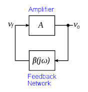
FIGURE1: OSCILLATOR BLOCK DIAGRAM.
Control theory states that the circuit will oscillate if |A*beta|=1 and arg(A*beta)=0
How can we test that using a circuit simulator?. How can we analyze the open loop function?
The great Middebrook Method
R. David Middlebrook was a professor of electrical engineering at the California that created a simple method to measure open loop gain. The great thing is that open loop gain could be measured without opening the loop. Using a current and voltage test sources at any point in the loop and making a simple vector operations, open loop gain and phase can be calculated.
In practice
I am not going to describe the formulation as it can be found in the litherature (see below). Here is the practical implementation of Middlebrook Method. QUCS free software is a great tool for doing it as equations can be used to do any needed calculation:
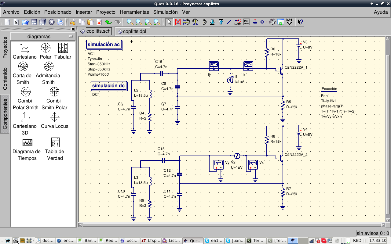
FIGURE2: MIDDLEBROOK METHOD VOLTAGE AND CURRENT TEST SOURCES. COLPITTS OSCILATOR.
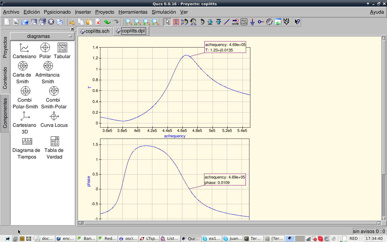
FIGURE3: MIDDLEBROOK METHOD. GAIN AND PHASE PLOTS. COLPITTS OSCILATOR.
Results
QUCS has an easy to use plotting feature. I have plotted open loop gain module and phase. Phase is cero at 469 kHz, with a gain of 1.23. As gain is greater than one, oscillations can be sustained. Using this method we can see if the circuit will oscillate and the effect of coil Q on open loop gain. For lower Q values the circuit just does not oscillate.
Bibliography
Measurement of loop gain in feedback systems. On Determining Loop Gain through Circuit Simulation. QEX Magazine.