RETIREMENT TRANSCEIVER, A TRANSCEIVER TO DIE IN PEACE
7 MHz SSB/CW ANALOG TRANSCEIVER
(2014-03-29)
Preface (2014-03-29)
Transceiver specifications
(2014-03-29)
Roadmap (2014-03-29)
Intermediate frequency crystal filter
(2014-03-29)
Getting crystal data (2014-03-30)
Choosing crystals (2014-03-30)
2800 Hz SSB Cohn Filter (2014-03-31)
Increasing filter bandwidth
(2014-04-01)
Impedance matching
(2014-04-03)
Filter simulations (2014-04-05)
CW Filter(2014-04-05)
Preface
Life is shorter than we think. When we are young we have the power, we really want to do things, messing with this and with the other, try everything. I have tried many things: CW, digital, HF bands, satellites, 144 MHz EME, home made CW and SSB transceivers. But...life passes quickly, too quickly. It is time to think.
We want to cover everything, all bands, all modes…... There comes a time when you realize you can not cover everything, it is impossible. Work, wife, children, time is limited. You feel frustrated.
I am 43. I often try to imagine myself at the age of 60 or 70. Will I have the same desire to do things as I have now? Probably not. I will have bad eyesight, poor pulse, bone pain, moodiness ...I will be tired of everything, hi...
Probably I will enjoy talking with friends in a relaxed QSO about the battles we did when we were young. I do not plan to buy more transceivers. Will I enjoy chatting using my Elecraft K3? Will I enjoy using my FT-897 asuming they are still alive? My other home made transceivers are not perfect, they have weak things that should be improved. They need a major redesign.
Will I die in peace that way? NO
I think that the great pleasure will be talking with my friends using a home made 7 MHz SSB / CW transceiver. A home made transceiver is something unique. Nobody but you owns it. You are the only person in the world that owns it. You are proud of it. You can do it, you know how it works, you can repair it, you do not need any external technical repairment service. You have solved all sort of problems during its building. You have improved your skills, you have learnt things. Learning is the key thing for me. Learning can not be bought with a hand full of euros.
If health allows it, I will have many years to finish it. In the mean time I will learn and enjoy many things. I will publish every building stage in my WEB page. I will not invent anything, everything is invented. I only have to pick and glue several good working RF blocks from the amateur litherature. There will not be energy restrictions or limitations of any kind that lead to poor performance. I want to get a good radio. I will be happy if I encourage others to do it.
The transceiver will not have too many bells and whistles, I want a transceiver that simply works with good specifications. I am interested in good RX dynamic range, I do not want the receiver to be overloaded by strong 41m band broadcasters at night. Good spectral purity in the TX part is also a concern. Here we have the desired starting point specifications, theese specifications could change during the design process. The design will be single band, 7 MHz only. If time allows it, it will be extended to other amateur radio bands, but now it is not a requirement.
Transceiver specifications
FRECUENCY COVERAGE: 7.000-7.200 MHz
MODES: SSB/CW
Receiver
RX type: Traditional analog single conversion superheterodine

RF PREAMP: switchable. High current biased BJT.

RF ATTENUATOR: 10 dB switchable.

RX MIXER: 7dBm LO diode ring, home made or Minicircuits.

LO Frequency: 17.000-17.200, Si-570 based

IF Frequency: 10 MHz. 2.8 KHz/400 Hz SSB/CW Bandwidth

BFO MIXER: 7 dBm LO diode ring, home made or Minicircuits.

AUDIO AMP: IC or discrete. Not decided yet.

DESIRED SFDR DYNAMIC RANGE \> 95 dB

MDS: Not critical. -136 dBm with preamp ON.
Transmitter
TX type: Analog single conversion.

MIC AMPLIFIER: Discrete or OPamp based.

SSB generator: Diode mixer

TX MIXER: 7dBm LO diode ring, not decided

TX POWER: 100W MOSFET

DISPLAY: 2X16 char LCD

DIAL: Rotary encoder

POWER SUPPLY: 13.8 V
CONSTRUCTION METHOD: ugly style over virgin PCB copper clad. Probably individual blocks in PCB boxes connected by coaxial cable and SMA connectors. If time allows it, build PCBs and use SMD parts.
ROADMAP
- IF CRYSTAL FILTER: 10 MHZ center frequency, 2800 Hz SSB BW, 400 Hz CW BW, 8 pole COHN/CHEBYCHEV. Cheap crystals selected from a batch of 100 bought at Ebay. Design with AADE software. Build and test with vector network analyzer. I will take care of getting good impedance match with preceding and following stages.
- AUDIO AMPLIFIER: IC or discrete. Not decided yet. I want to test a discrete 3 BJT design from the EMRFD book before using the boring LM386.
- BFO MIXER: Diode ring, probably home made.
- BFO: Crystal based, one or two BJT.
- IF AMPLIFIER AND AGC: W7ZOI hybrid cascoded design. 55 dB gain, 100 dB AGC action. I like it but a bit complicated. We’ll see.
- MIXER: Minicircuits or home made diode ring mixer. If home made, using selected schottky diodes from the junk box, ferrite transformers.
- LO: Add a LPF and amplify the signal lñof my Si-570 board from the "Reinventing the Wheel SDR" to the 7 dBm level.
- POST MIXER AMPLIFIER: High biased BJT followed by attenuator from EMRFD. I have tested it in previous proyects and it just works.
- RF AMP: High biased BJT. RF filter.
- DISPLAY FOR LO BOARD. Add a 2x16 character display and all the bell and whistles.
- MIC AMPLIFIER AND DSB MODULATOR:
- IF FILTER: Same filter used for receiving.
- TX MIXER: I do not know
- POWER AMPLIFIER: MOSFET
- LOW PASS FILTER.
Any comments and suggestions will be of course appreciated.
Let's start this amazing experience!
73, Ramiro, EA4NZ
LET'S START WITH THE INTERMEDIATE FREQUENCY CRYSTAL FILTER (2014-03-29)
Two weeks ago I ordered on Ebay 100 units of 10 MHz crystals. Price was 9.8$ ! I received 101 units.
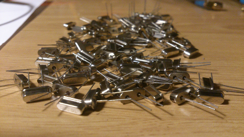
FIGURE1: A BUNCH OF 101 UNITS OF 10 MHz QUARTZ CRYSTALS AS RECEIVED FROM EBAY
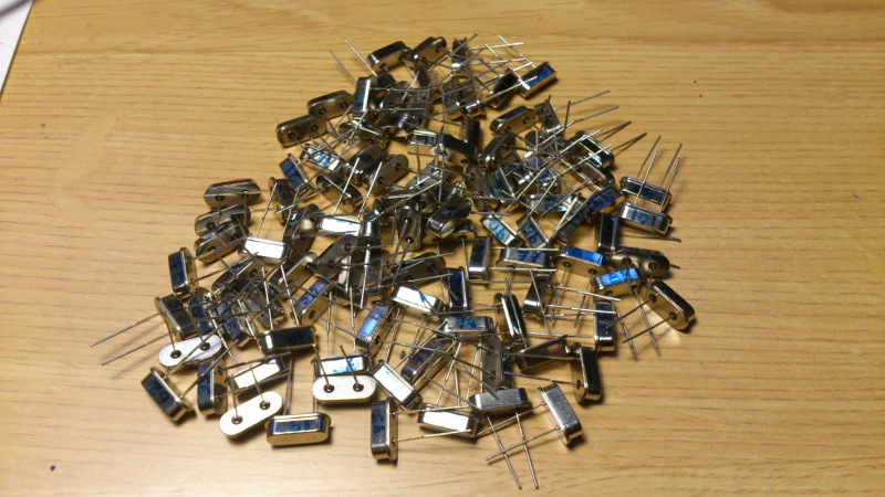
FIGURE2: CRYSTALS WERE CAREFULLY LABELED
FIGURE3: VNWA3 VECTOR NETWORK ANALYZER WAS CALIBRATED USING LOAD, SHORT, OPEN AND THRU CALIBRATION STANDARDS AFTER A 30 MIN WARM UP PERIOD
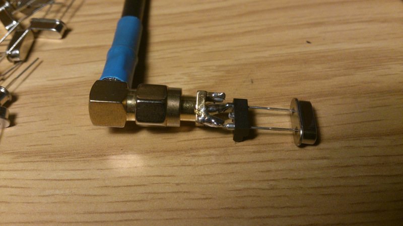
FIGURE4: A CRYSTAL IS ATTACHED TO VNWA3 TX PORT
Getting crystal data
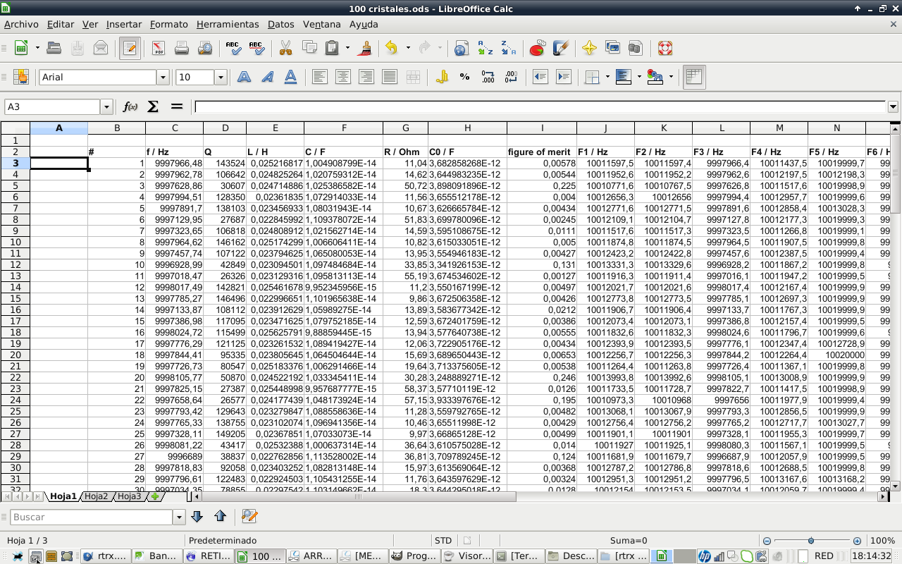
FIGURE5: AFTER AN HOUR AND A HALF OF CRYSTAL TESTING, A LIBREOFFICE SPREADSHEET WITH DATA WAS GENERATED.
Crystal extracted parameters are:
Series frequency
Q
Series inductance
Series capacitance
Series resistance
Parallel capacitance
It is interesting to note that crystal parameters have a big spread of values. Q ranges from 25000 to 150000. I really do not know if this Q spread values are normal among crystals or is due to poor manufacturing quality control. I will analyze this data in order to choose the best group of crystals for my intermediate frequency filter. That is all for now.
Choosing crystals
EMRFD book states that frequency spread of crystals should be smaller than 5% to 10% of the filter bandwith. So, for a 2800 Hz wide SSB filter, crystal frequency spread should be 140 to 280 Hz from the nominal frequency. For a 400 Hz filter the requirements are more restrictive, crystals resonant series frequency should be no more than 20 to 40 Hz off the nominal frequency
I have sorted spreadsheet data by crystal series resonant frequency and grouped crystals with closest resonant series frequency with the same color. I have taken into account crystal Q, discarding low Q crystals. Maximum frequency difference among crystals in the filter is shown in the first column.
| filter F spread (Hz) | # | f / Hz | Q | L / H | C / F | R / Ohm | C0 / F | figure of merit |
| 56 | 9998138 | 136999 | 0,03 | 1,006739369E-14 | 11,54 | 3,630117647E-12 | 0,01 | |
| 67 | 9998129 | 107333 | 0,03 | 1,002762047E-14 | 14,79 | 3,702613765E-12 | 0,03 | |
| 46 | 9998120 | 12758 | 0,03 | 9,467226717E-15 | 131,8 | 3,921623182E-12 | 2,25 | |
| 20 | 9998106 | 50870 | 0,02 | 1,033345411E-14 | 30,28 | 3,248889271E-12 | 0,25 | |
| 58 | 9998083 | 143335 | 0,02 | 1,026686949E-14 | 10,82 | 3,639191914E-12 | 0,01 | |
| 26 | 9998081 | 43417 | 0,03 | 1,000637314E-14 | 36,64 | 3,610575028E-12 | 0,01 | |
| 53 | 9998049 | 26664 | 0,03 | 9,924579727E-15 | 60,16 | 3,549405888E-12 | 0,01 | |
| 35 | 9998047 | 136590 | 0,03 | 1,008314638E-14 | 11,56 | 3,570721406E-12 | 0,01 | |
| 16 | 9998025 | 115499 | 0,03 | 9,88859445E-15 | 13,94 | 3,577640738E-12 | 0,01 | |
| 120,0 | 12 | 9998017 | 142821 | 0,03 | 9,952345956E-15 | 11,2 | 3,550167199E-12 | 0 |
| 45 | 9998003 | 94815 | 0,02 | 1,045241588E-14 | 16,06 | 3,490968635E-12 | 0,02 | |
| 4 | 9997995 | 128350 | 0,02 | 1,072914033E-14 | 11,56 | 3,655512178E-12 | 0 | |
| 59 | 9997992 | 123134 | 0,03 | 1,009073127E-14 | 12,81 | 3,690663762E-12 | 0,01 | |
| 85 | 9997969 | 136162 | 0,03 | 1,001311381E-14 | 11,68 | 3,591467806E-12 | 0 | |
| 69 | 9997967 | 134545 | 0,02 | 1,047730034E-14 | 11,29 | 3,569592931E-12 | 0 | |
| 1 | 9997966 | 143524 | 0,03 | 1,004908799E-14 | 11,04 | 3,682858268E-12 | 0,01 | |
| 8 | 9997965 | 146162 | 0,03 | 1,006606411E-14 | 10,82 | 3,615033051E-12 | 0,01 | |
| 2 | 9997963 | 106642 | 0,02 | 1,020759312E-14 | 14,62 | 3,644983235E-12 | 0,01 | |
| 51 | 9997960 | 147748 | 0,03 | 1,0086928E-14 | 10,68 | 3,69911514E-12 | 0,01 | |
| 37,4 | 95 | 9997957 | 139535 | 0,02 | 1,044536519E-14 | 10,92 | 3,57408008E-12 | 0,01 |
| 61 | 9997954 | 109233 | 0,02 | 1,06752821E-14 | 13,65 | 3,630077261E-12 | 0 | |
| 37 | 9997951 | 129370 | 0,03 | 9,863294202E-15 | 12,48 | 3,651418802E-12 | 0,01 | |
| 98 | 9997950 | 115745 | 0,02 | 1,075558797E-14 | 12,79 | 3,661311085E-12 | 0,01 | |
| 40 | 9997943 | 95597 | 0,02 | 1,034783398E-14 | 16,09 | 3,64044238E-12 | 0,03 | |
| 70 | 9997936 | 134263 | 0,02 | 1,046087535E-14 | 11,33 | 3,676843235E-12 | 0 | |
| 94 | 9997933 | 120335 | 0,02 | 1,018634415E-14 | 12,99 | 3,612498251E-12 | 0,01 | |
| 55 | 9997930 | 126751 | 0,02 | 1,065663494E-14 | 11,79 | 3,682970415E-12 | 0 | |
| 32 | 9997925 | 147488 | 0,02 | 1,027411662E-14 | 10,51 | 3,713664075E-12 | 0 | |
| 68 | 9997924 | 128615 | 0,02 | 1,061363366E-14 | 11,66 | 3,637815472E-12 | 0 | |
| 97 | 9997909 | 150085 | 0,02 | 1,031763444E-14 | 10,28 | 3,69824663E-12 | 0,01 | |
| 36 | 9997909 | 101791 | 0,02 | 1,059067278E-14 | 14,77 | 3,808621529E-12 | 0,16 | |
| 5 | 9997892 | 138103 | 0,02 | 1,08031943E-14 | 10,67 | 3,626665784E-12 | 0 | |
| 44,2 | 99 | 9997892 | 137717 | 0,03 | 9,800533978E-15 | 11,79 | 3,656749458E-12 | 0,01 |
| 80 | 9997884 | 115925 | 0,02 | 1,067936688E-14 | 12,86 | 3,606741814E-12 | 0 | |
| 84 | 9997882 | 66963 | 0,02 | 1,035761664E-14 | 22,95 | 3,548057739E-12 | 0,01 | |
| 33 | 9997880 | 102420 | 0,02 | 1,075195891E-14 | 14,46 | 3,603640128E-12 | 0,01 | |
| 66 | 9997872 | 97594 | 0,02 | 1,109208896E-14 | 14,71 | 3,670724316E-12 | 0 | |
| 47 | 9997863 | 142820 | 0,02 | 1,075498419E-14 | 10,36 | 3,636268208E-12 | 0 | |
| 100 | 9997860 | 120631 | 0,02 | 1,043778914E-14 | 12,64 | 3,611271355E-12 | 0,01 | |
| 41 | 9997848 | 131354 | 0,02 | 1,057834458E-14 | 11,46 | 3,634876174E-12 | 0 | |
| 18 | 9997844 | 95335 | 0,02 | 1,064504644E-14 | 15,69 | 3,689650443E-12 | 0,01 | |
| 92 | 9997833 | 130315 | 0,02 | 1,08459783E-14 | 11,26 | 3,606549857E-12 | 0 | |
| 77 | 9997829 | 116226 | 0,02 | 1,079300472E-14 | 12,69 | 3,585567782E-12 | 0 | |
| 89 | 9997826 | 31728 | 0,02 | 1,040608826E-14 | 48,22 | 3,852281787E-12 | 0,35 | |
| 59,1 | 34 | 9997825 | 139730 | 0,02 | 1,061079194E-14 | 10,74 | 3,713129309E-12 | 0,01 |
| 21 | 9997825 | 27387 | 0,03 | 9,957687777E-15 | 58,37 | 3,57710119E-12 | 0,01 | |
| 64 | 9997822 | 100623 | 0,02 | 1,077488915E-14 | 14,68 | 3,632542818E-12 | 0,01 | |
| 28 | 9997819 | 92058 | 0,02 | 1,082813148E-14 | 15,97 | 3,613569064E-12 | 0 | |
| 82 | 9997815 | 118834 | 0,02 | 1,070210363E-14 | 12,52 | 3,638694106E-12 | 0 | |
| 62 | 9997814 | 125012 | 0,02 | 1,080003084E-14 | 11,79 | 3,603570769E-12 | 0 | |
| 87 | 9997809 | 128303 | 0,02 | 1,089000445E-14 | 11,39 | 3,724771612E-12 | 0 | |
| 43 | 9997797 | 131939 | 0,02 | 1,073956779E-14 | 11,23 | 3,541775526E-12 | 0 | |
| 29 | 9997797 | 122483 | 0,02 | 1,105431255E-14 | 11,76 | 3,643597629E-12 | 0 | |
| 23 | 9997793 | 129643 | 0,02 | 1,088558636E-14 | 11,28 | 3,559792765E-12 | 0 | |
| 91 | 9997790 | 131921 | 0,02 | 1,095093031E-14 | 11,02 | 3,647664596E-12 | 0 | |
| 75 | 9997787 | 108053 | 0,02 | 1,089182381E-14 | 13,53 | 3,678679622E-12 | 0 | |
| 30,1 | 13 | 9997785 | 146496 | 0,02 | 1,101965638E-14 | 9,86 | 3,672506358E-12 | 0 |
| 44 | 9997780 | 133069 | 0,02 | 1,085721312E-14 | 11,02 | 3,602538713E-12 | 0 | |
| 48 | 9997777 | 74224 | 0,02 | 1,045287295E-14 | 20,52 | 3,416299478E-12 | 0,1 | |
| 17 | 9997776 | 121125 | 0,02 | 1,089419427E-14 | 12,06 | 3,722905176E-12 | 0 | |
| 86 | 9997773 | 85903 | 0,02 | 1,025060245E-14 | 18,08 | 3,668409966E-12 | 0,01 | |
| 24 | 9997765 | 138755 | 0,02 | 1,096941356E-14 | 10,46 | 3,65511998E-12 | 0 | |
| 39 | 9997765 | 50118 | 0,02 | 1,107675737E-14 | 28,68 | 3,639285779E-12 | 0,01 | |
| 63 | 9997746 | 122685 | 0,02 | 1,112694053E-14 | 11,66 | 3,660918069E-12 | 0 | |
| 96 | 9997732 | 115314 | 0,02 | 1,108179608E-14 | 12,46 | 3,724398869E-12 | 0 | |
| 19 | 9997727 | 80547 | 0,03 | 1,006291466E-14 | 19,64 | 3,713375605E-12 | 0,01 | |
| 58,9 | 101 | 9997717 | 128761 | 0,03 | 9,909530043E-15 | 12,48 | 3,652089137E-12 | 0,01 |
| 71 | 9997702 | 76899 | 0,03 | 1,002032053E-14 | 20,66 | 3,596016674E-12 | 0 | |
| 22 | 9997659 | 26577 | 0,02 | 1,048173924E-14 | 57,15 | 3,933397676E-12 | 0,2 | |
| 3 | 9997629 | 30607 | 0,02 | 1,025386582E-14 | 50,72 | 3,898091896E-12 | 0,23 | |
| 42 | 9997590 | 83350 | 0,02 | 1,10165977E-14 | 17,34 | 3,829251278E-12 | 0,08 | |
| 9 | 9997458 | 107122 | 0,02 | 1,065080053E-14 | 13,95 | 3,554946183E-12 | 0 | |
| 72 | 9997396 | 91047 | 0,03 | 9,900054269E-15 | 17,66 | 3,606820243E-12 | 0,13 | |
| 15 | 9997387 | 117095 | 0,02 | 1,079752185E-14 | 12,59 | 3,672401759E-12 | 0 | |
| 52 | 9997381 | 119854 | 0,02 | 1,10590321E-14 | 12,01 | 3,672836065E-12 | 0 | |
| 73 | 9997361 | 45704 | 0,02 | 1,046780346E-14 | 33,28 | 3,871104694E-12 | 0,12 | |
| 38 | 9997356 | 115225 | 0,02 | 1,052362158E-14 | 13,13 | 3,662417877E-12 | 0 | |
| 93 | 9997341 | 101262 | 0,02 | 1,096763432E-14 | 14,33 | 3,629418206E-12 | 0 | |
| 25 | 9997328 | 149205 | 0,02 | 1,07033073E-14 | 9,97 | 3,66865128E-12 | 0 | |
| 7 | 9997324 | 106818 | 0,02 | 1,021562714E-14 | 14,59 | 3,595108675E-12 | 0,01 | |
| 31 | 9997310 | 142124 | 0,02 | 1,064907826E-14 | 10,52 | 3,630050029E-12 | 0 | |
| 167,3 | 88 | 9997290 | 143190 | 0,02 | 1,024254199E-14 | 10,85 | 3,714439486E-12 | 0,01 |
| 76 | 9997287 | 95154 | 0,02 | 1,100821514E-14 | 15,2 | 3,648453096E-12 | 0 | |
| 54 | 9997280 | 128177 | 0,02 | 1,040670849E-14 | 11,93 | 3,709180089E-12 | 0,01 | |
| 65 | 9997170 | 59852 | 0,02 | 1,095861312E-14 | 24,27 | 3,7486007E-12 | 0,17 | |
| 78 | 9997163 | 120277 | 0,02 | 1,047717233E-14 | 12,63 | 3,739086741E-12 | 0 | |
| 57 | 9997158 | 93435 | 0,02 | 1,044674763E-14 | 16,31 | 2,948145332E-12 | 0,26 | |
| 79 | 9997154 | 53226 | 0,02 | 1,108472789E-14 | 26,98 | 3,637187802E-12 | 0,01 | |
| 90 | 9997151 | 42551 | 0,02 | 1,037380486E-14 | 36,07 | 3,07999608E-12 | 0,47 | |
| 14 | 9997134 | 108112 | 0,02 | 1,05989275E-14 | 13,89 | 3,583677342E-12 | 0,02 | |
| 6 | 9997130 | 27687 | 0,02 | 1,109378072E-14 | 51,83 | 3,699780096E-12 | 0 | |
| 81 | 9997109 | 68153 | 0,02 | 1,132114917E-14 | 20,63 | 3,834498914E-12 | 0,16 | |
| 49 | 9997088 | 46915 | 0,02 | 1,0310441E-14 | 32,91 | 3,49906665E-12 | 0,95 | |
| 74 | 9997059 | 31876 | 0,02 | 1,106681527E-14 | 45,13 | 3,64762006E-12 | 0 | |
| 50 | 9997054 | 60720 | 0,02 | 1,097743883E-14 | 23,88 | 3,936661472E-12 | 0,12 | |
| 30 | 9997034 | 78855 | 0,02 | 1,103149662E-14 | 18,3 | 3,644295018E-12 | 0,01 | |
| 11 | 9997018 | 26326 | 0,02 | 1,095813113E-14 | 55,19 | 3,674534602E-12 | 0 | |
| 60 | 9996990 | 104116 | 0,02 | 1,088729701E-14 | 14,04 | 3,660861391E-12 | 0 | |
| 83 | 9996968 | 74303 | 0,02 | 1,098314451E-14 | 19,51 | 3,587863677E-12 | 0,02 | |
| 10 | 9996929 | 42849 | 0,02 | 1,097484684E-14 | 33,85 | 3,341926153E-12 | 0,13 | |
| 27 | 9996689 | 38837 | 0,02 | 1,113528002E-14 | 36,81 | 3,709789245E-12 | 0,12 |
The definitive table discarding low Q crystals looks like this:
| filter F spread (Hz) | # | f / Hz | Q | L / H | C / F | R / Ohm | C0 / F | figure of merit |
| 56 | 9998138 | 136999 | 0,0252 | 1,006739369E-14 | 11,54 | 3,630117647E-12 | 0,0051 | |
| 67 | 9998129 | 107333 | 0,0253 | 1,002762047E-14 | 14,79 | 3,702613765E-12 | 0,0262 | |
| 58 | 9998083 | 143335 | 0,0247 | 1,026686949E-14 | 10,82 | 3,639191914E-12 | 0,0050 | |
| 35 | 9998047 | 136590 | 0,0251 | 1,008314638E-14 | 11,56 | 3,570721406E-12 | 0,0058 | |
| 16 | 9998025 | 115499 | 0,0256 | 9,88859445E-15 | 13,94 | 3,577640738E-12 | 0,0056 | |
| 120,0 | 12 | 9998017 | 142821 | 0,0255 | 9,952345956E-15 | 11,2 | 3,550167199E-12 | 0,0050 |
| 4 | 9997995 | 128350 | 0,0236 | 1,072914033E-14 | 11,56 | 3,655512178E-12 | 0,0040 | |
| 59 | 9997992 | 123134 | 0,0251 | 1,009073127E-14 | 12,81 | 3,690663762E-12 | 0,0057 | |
| 85 | 9997969 | 136162 | 0,0253 | 1,001311381E-14 | 11,68 | 3,591467806E-12 | 0,0046 | |
| 69 | 9997967 | 134545 | 0,0242 | 1,047730034E-14 | 11,29 | 3,569592931E-12 | 0,0042 | |
| 1 | 9997966 | 143524 | 0,0252 | 1,004908799E-14 | 11,04 | 3,682858268E-12 | 0,0100 | |
| 8 | 9997965 | 146162 | 0,0252 | 1,006606411E-14 | 10,82 | 3,615033051E-12 | 0,0050 | |
| 51 | 9997960 | 147748 | 0,0251 | 1,0086928E-14 | 10,68 | 3,69911514E-12 | 0,0058 | |
| 37,4 | 95 | 9997957 | 139535 | 0,0243 | 1,044536519E-14 | 10,92 | 3,57408008E-12 | 0,0051 |
| 70 | 9997936 | 134263 | 0,0242 | 1,046087535E-14 | 11,33 | 3,676843235E-12 | 0,0047 | |
| 94 | 9997933 | 120335 | 0,0249 | 1,018634415E-14 | 12,99 | 3,612498251E-12 | 0,0054 | |
| 55 | 9997930 | 126751 | 0,0238 | 1,065663494E-14 | 11,79 | 3,682970415E-12 | 0,0044 | |
| 32 | 9997925 | 147488 | 0,0247 | 1,027411662E-14 | 10,51 | 3,713664075E-12 | 0,0050 | |
| 68 | 9997924 | 128615 | 0,0239 | 1,061363366E-14 | 11,66 | 3,637815472E-12 | 0,0047 | |
| 97 | 9997909 | 150085 | 0,0246 | 1,031763444E-14 | 10,28 | 3,69824663E-12 | 0,0052 | |
| 5 | 9997892 | 138103 | 0,0235 | 1,08031943E-14 | 10,67 | 3,626665784E-12 | 0,0043 | |
| 44,2 | 99 | 9997892 | 137717 | 0,0259 | 9,800533978E-15 | 11,79 | 3,656749458E-12 | 0,0069 |
| 80 | 9997884 | 115925 | 0,0237 | 1,067936688E-14 | 12,86 | 3,606741814E-12 | 0,0045 | |
| 33 | 9997880 | 102420 | 0,0236 | 1,075195891E-14 | 14,46 | 3,603640128E-12 | 0,0079 | |
| 47 | 9997863 | 142820 | 0,0236 | 1,075498419E-14 | 10,36 | 3,636268208E-12 | 0,0047 | |
| 100 | 9997860 | 120631 | 0,0243 | 1,043778914E-14 | 12,64 | 3,611271355E-12 | 0,0055 | |
| 41 | 9997848 | 131354 | 0,0240 | 1,057834458E-14 | 11,46 | 3,634876174E-12 | 0,0048 | |
| 92 | 9997833 | 130315 | 0,0234 | 1,08459783E-14 | 11,26 | 3,606549857E-12 | 0,0049 | |
| 77 | 9997829 | 116226 | 0,0235 | 1,079300472E-14 | 12,69 | 3,585567782E-12 | 0,0043 | |
| 59,1 | 34 | 9997825 | 139730 | 0,0239 | 1,061079194E-14 | 10,74 | 3,713129309E-12 | 0,0051 |
| 82 | 9997815 | 118834 | 0,0237 | 1,070210363E-14 | 12,52 | 3,638694106E-12 | 0,0046 | |
| 62 | 9997814 | 125012 | 0,0235 | 1,080003084E-14 | 11,79 | 3,603570769E-12 | 0,0044 | |
| 87 | 9997809 | 128303 | 0,0233 | 1,089000445E-14 | 11,39 | 3,724771612E-12 | 0,0046 | |
| 43 | 9997797 | 131939 | 0,0236 | 1,073956779E-14 | 11,23 | 3,541775526E-12 | 0,0049 | |
| 29 | 9997797 | 122483 | 0,0229 | 1,105431255E-14 | 11,76 | 3,643597629E-12 | 0,0032 | |
| 23 | 9997793 | 129643 | 0,0233 | 1,088558636E-14 | 11,28 | 3,559792765E-12 | 0,0048 | |
| 91 | 9997790 | 131921 | 0,0231 | 1,095093031E-14 | 11,02 | 3,647664596E-12 | 0,0041 | |
| 30,1 | 13 | 9997785 | 146496 | 0,0230 | 1,101965638E-14 | 9,86 | 3,672506358E-12 | 0,0043 |
| 17 | 9997776 | 121125 | 0,0233 | 1,089419427E-14 | 12,06 | 3,722905176E-12 | 0,0043 | |
| 24 | 9997765 | 138755 | 0,0231 | 1,096941356E-14 | 10,46 | 3,65511998E-12 | 0,0043 | |
| 63 | 9997746 | 122685 | 0,0228 | 1,112694053E-14 | 11,66 | 3,660918069E-12 | 0,0046 | |
| 96 | 9997732 | 115314 | 0,0229 | 1,108179608E-14 | 12,46 | 3,724398869E-12 | 0,0037 | |
| 58,9 | 101 | 9997717 | 128761 | 0,0256 | 9,909530043E-15 | 12,48 | 3,652089137E-12 | 0,0061 |
| 9 | 9997458 | 107122 | 0,0238 | 1,065080053E-14 | 13,95 | 3,554946183E-12 | 0,0043 | |
| 15 | 9997387 | 117095 | 0,0235 | 1,079752185E-14 | 12,59 | 3,672401759E-12 | 0,0039 | |
| 52 | 9997381 | 119854 | 0,0229 | 1,10590321E-14 | 12,01 | 3,672836065E-12 | 0,0045 | |
| 38 | 9997356 | 115225 | 0,0241 | 1,052362158E-14 | 13,13 | 3,662417877E-12 | 0,0042 | |
| 93 | 9997341 | 101262 | 0,0231 | 1,096763432E-14 | 14,33 | 3,629418206E-12 | 0,0045 | |
| 25 | 9997328 | 149205 | 0,0237 | 1,07033073E-14 | 9,97 | 3,66865128E-12 | 0,0050 | |
| 31 | 9997310 | 142124 | 0,0238 | 1,064907826E-14 | 10,52 | 3,630050029E-12 | 0,0047 | |
| 167,3 | 88 | 9997290 | 143190 | 0,0247 | 1,024254199E-14 | 10,85 | 3,714439486E-12 | 0,0054 |
So we have 7 possible crystal filters:
-6 pole crystal suitable for SSB -8 pole crystal suitable for CW or SSB -8 pole crystal suitable for CW or SSB -8 pole crystal suitable for CW or SSB -8 pole crystal suitable for CW or SSB -5 pole crystal suitable for CW or SSB -8 pole crystal suitable for SSB
2800 Hz SSB Cohn Filter
The folowing table shows selected crystals for this filter, with average values at the bottom:
| filter F spread (Hz) | # | f / Hz | Q | L / H | C / F | R / Ohm | C0 / F |
| 80 | 9997884 | 115925 | 2,37289507E-02 | 1,067936688E-14 | 12,86 | 3,606741814E-12 | |
| 33 | 9997880 | 102420 | 2,35687642E-02 | 1,075195891E-14 | 14,46 | 3,603640128E-12 | |
| 47 | 9997863 | 142820 | 2,35622136E-02 | 1,075498419E-14 | 10,36 | 3,636268208E-12 | |
| 100 | 9997860 | 120631 | 2,42782628E-02 | 1,043778914E-14 | 12,64 | 3,611271355E-12 | |
| 41 | 9997848 | 131354 | 2,39557350E-02 | 1,057834458E-14 | 11,46 | 3,634876174E-12 | |
| 92 | 9997833 | 130315 | 2,33646771E-02 | 1,08459783E-14 | 11,26 | 3,606549857E-12 | |
| 77 | 9997829 | 116226 | 2,34793737E-02 | 1,079300472E-14 | 12,69 | 3,585567782E-12 | |
| 59,1 | 34 | 9997825 | 139730 | 2,38825874E-02 | 1,061079194E-14 | 10,74 | 3,713129309E-12 |
| AVERAGE | 9997853 | 124928 | 0,023727571 | 1,06815273E-14 | 12,1 | 3,62475558E-12 |
Average crystal parameters were used as input values in AADE Filter Desgin software. A Cohn ladder filter, 8 poles and 2800 Hz bandwidth filter was selected.
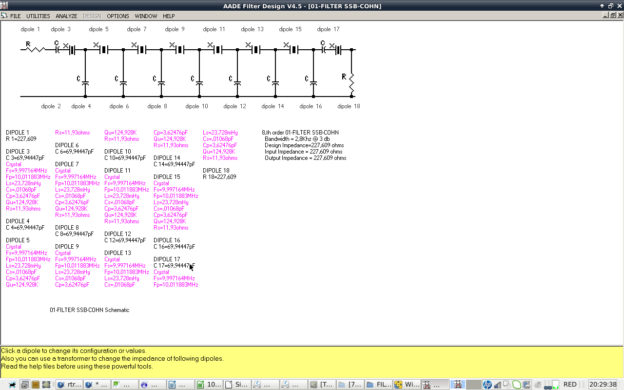
FIGURE6: 2800 HZ BW COHN FILTER DESIGNED USING AADE SOFTWARE.
Input and output impedances are 228 ohms, we will transform them to 50 ohms later. Predicted power gain, return loss and group delay graphs are shown below:
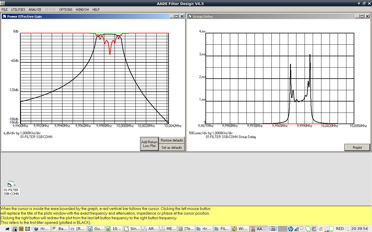
FIGURE6: FILTER POWER GAIN, RETURN LOSS AND GROUP DELAY GRAPHS.
A closeup of the filter passband shape:
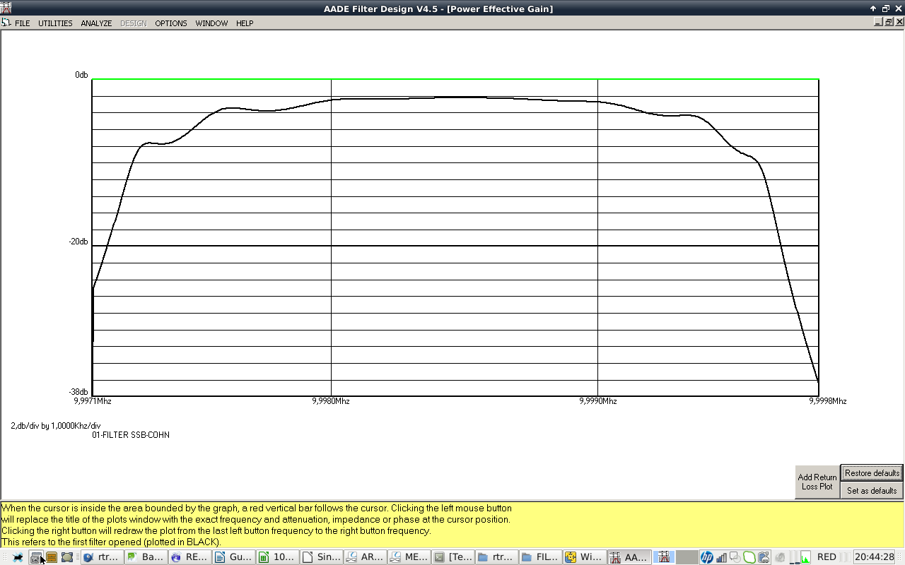
FIGURE8: A CLOSEUP OF FILTER PASSBAND SHAPE.
Filter measurement
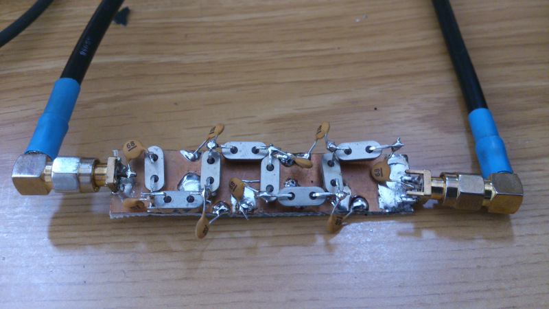
FIGURE9a: FILTER CONNECTED TO TX AN RX VECTOR ANALYZER PORTS
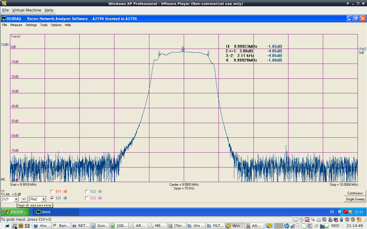
FIGURE9: MEASURED FILTER S11 AND S21 PARAMETERS ON A 50 OHM SYSTEM. VNWA3 SOFTWARE MAKES TRANSFORMATION TO 227 OHM INPUT AND OUTPUT IMPEDANCES. -3dB BW
Filter shape is similar to the calculated values. Filter attenuation at passband center is 1.85 dB. Filter BW is 2.1 kHz at -3 dB, a bit narrow. I do not particulary like ripple shape of Cohn filters. Passband has that ripple shape at high order filters. Anyway, they are easy to build.
Stopband attenuation falls into the limits of the vector analyzer dynamic range. In order to improve stop band attenuation, crystal shields should be connected to ground. I will make that experiment later although I cannot see what happens below -80 dB.
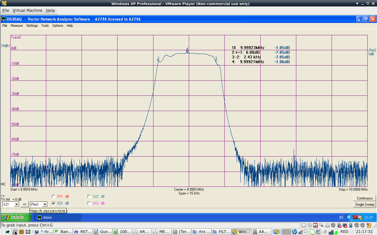
FIGURE10: -6 dB BW
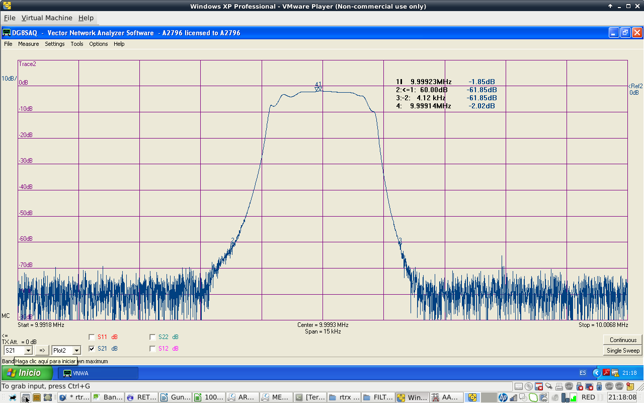
FIGURE11: -60 dB BW
2.8 kHz SSB Cohn filter measured specifications (68 pF coupling capacitors)
design -3dB BW: 2800 Hz
poles: 8
design output impedance: 228 ohms
design input impedance: 228 ohms
passband center attenuation: -1.85 dB
Bandwidth: 2.1kHz @ -3dB
Bandwidth: 2.43kHz @ -6dB
Bandwidth: 4.12kHz @ -60dB
Shape factor: 4.12/2.43= 1.69  (-6dB/-60dB)
I have noticed that measured filter -3dB bandwidth (2100 Hz) is narrower than the specified 2800 Hz . The reason is the paralel capacitance of crystals. AADE software does not take them into account in the design form, so measured BW is always narrower than the designed filter. On the other hand, AADE Analyze feature does take them in account, so that predicted filter passband shapes are very close to the measured ones.
In order to increase filter BW to the desired 2800 Hz, I will reduce capacitors values.
Increasing filter bandwidth
To increase BW, coupling capacitor values were reduced from 68 to 47 pF in AADE software. Filter impedance changed also, so I adjusted input and output resistors in AADE software until I got a good passband shape.
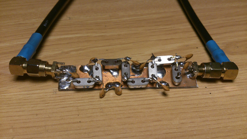
FIGURE12: NEW FILTER WITH REDUCED CAPACITOR VALUES. 47 pF
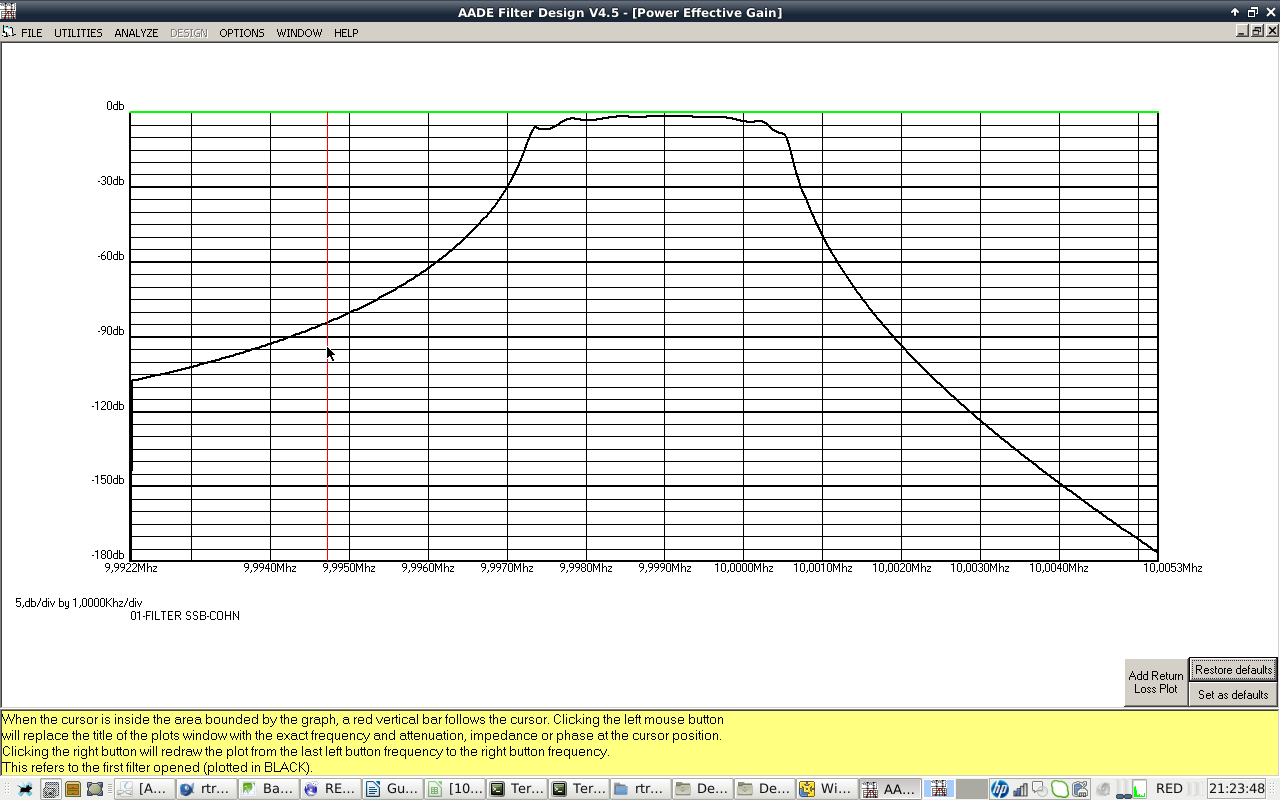
FIGURE13: SIMULATION OF FILTER PASSBAND
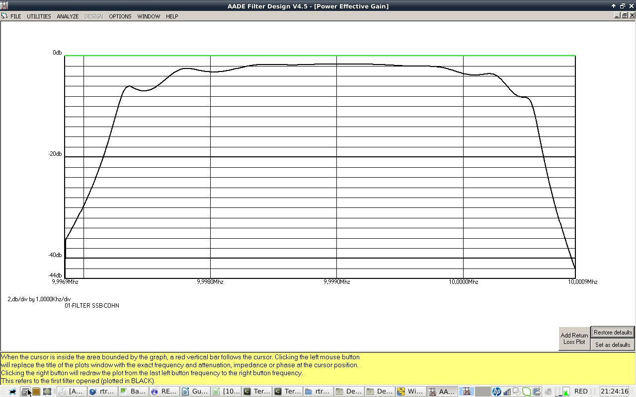
FIGURE14: CLOSEUP OF FILTER PASSBAND
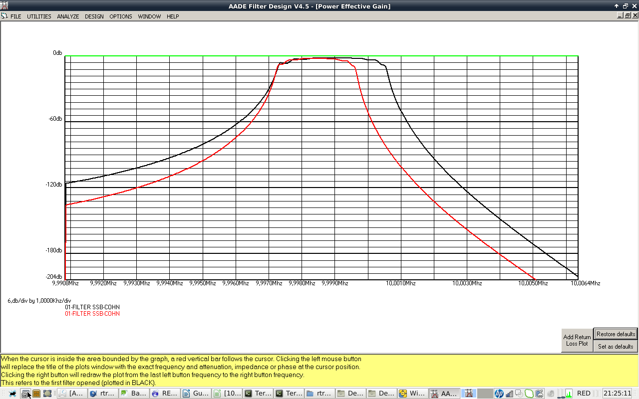
FIGURE15: COMPARING FILTERS WITH 47pF (BLACK) AND 68 pF (RED) COUPLING CAPACITORS

FIGURE16: FILTER -3dB BW MEASUREMENT
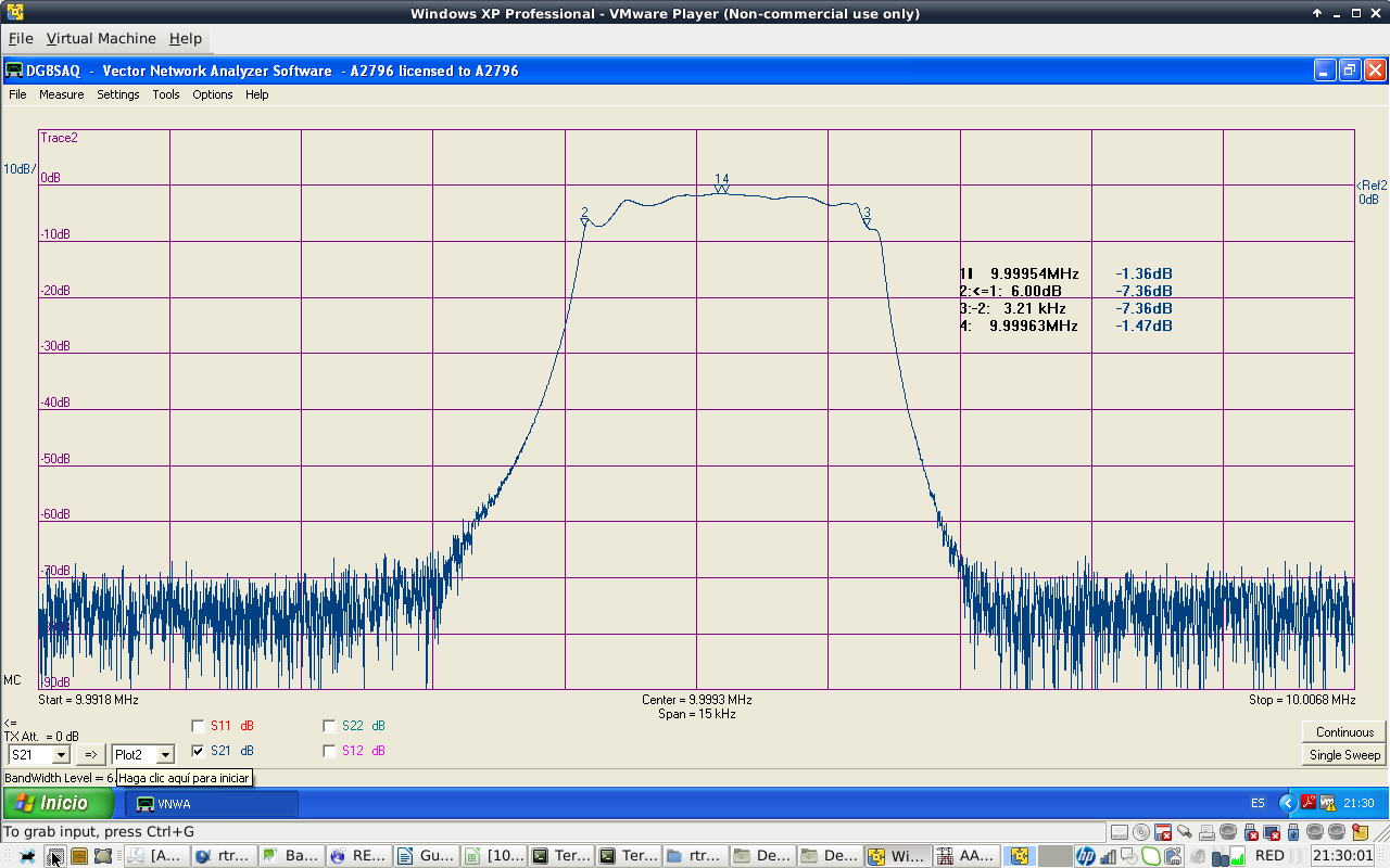
FIGURE17: FILTER -6dB BW MEASUREMENT
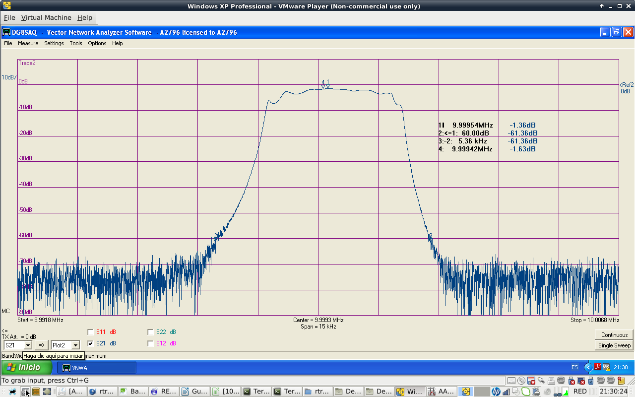
FIGURE18: FILTER -60dB BW MEASUREMENT
2.8 kHz SSB Cohn filter measured specifications (47pF coupling capacitors)
design -3dB BW: 2800 Hz
poles: 8
design output impedance: 340 ohms
design input impedance: 340 ohms
passband center attenuation: -1.36 dB
Bandwidth: 2.76kHz @ -3dB
Bandwidth: 3.21kHz @ -6dB
Bandwidth: 5.36 kHz @ -60dB
Shape factor: 5.36/3.21= 1.67   (-6dB/-60dB)
Impedance matching
Input and output filter impedances are 340 ohms. To transform them to 50 ohms, I used an autotransformer. Impedance ratio is 340/50=6.8. Turns ratio is sqrt(6.8)=2.60.
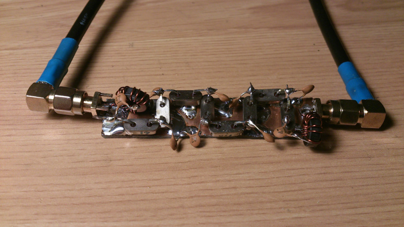
FIGURE19: 13:5 TURNS RATIO AUTOTRANSFORMERS AT FILTER INPUT AND OUPUT
A common rule of thumb is using windings wich reactance is four times the impedance at that side of the transformer. I used here an even bigger value. I wound 13 turns on a FT-37-43 toroid, tapped at the 5th turn to get the low impedance output. 13 turns on that toroid are 59.15 uH inductance and a reactance of +j3716 ohms, more than 10 times the impedance of the filter. 5 turns are 8.75uH, +j550 ohms, more than 10 times the impedance at that side, 50 ohms. So, It should work.
I made a sweep and I got the expected result. This time I did not have to use the "matching tool" on VNWA3 software, the impedance transformation was done at the transformers.
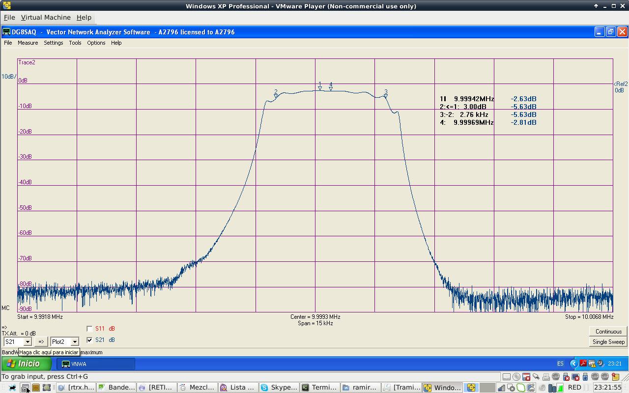
FIGURE20: -3dB BANDWIDTH
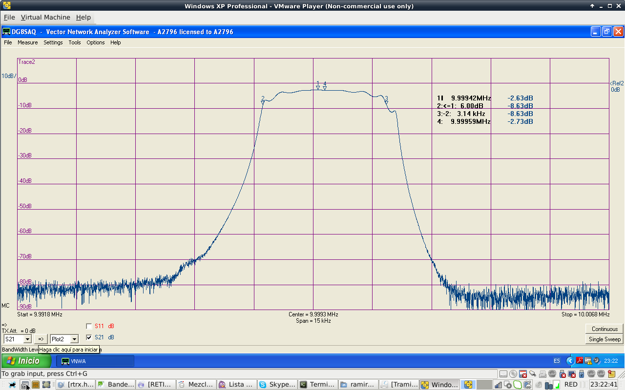
FIGURE21: -6dB BANDWIDTH
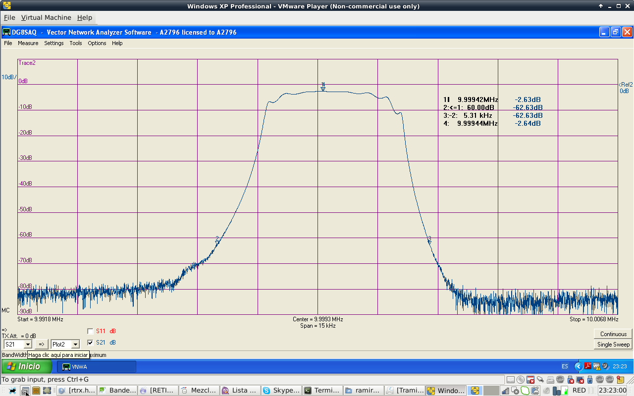
FIGURE22: -60dB BANDWIDTH
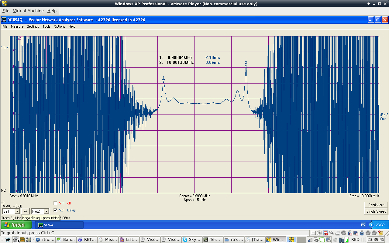
FIGURE23: GROUP DELAY
2.8 kHz SSB Cohn filter measured specifications (47pF coupling capacitors and matching transformers)
design -3dB BW: 2800 Hz
poles: 8
design output impedance: 340 ohms. Transformer matched to 50 ohms.
design input impedance: 340 ohms. Transformer matched to 50 ohms.
passband center attenuation: -2.63 dB
Bandwidth: 2.76kHz @ -3dB
Bandwidth: 3.14kHz @ -6dB
Bandwidth: 5.31 kHz @ -60dB
Shape factor: 5.31/3.14= 1.69   (-6dB/-60dB)
We have 1.27 dB more losses than without the transformers. Passband shape is a bit worse on the high frequency end. Group delay is not uniform along the passband.
Filter simulations
What can be done to improve this kind of filter? Nothing, I think..., but just to be sure, I simulated the circuit using QUCS software with average measured part values. The results are very close to the measured ones. QUCS is a powerful tool due to its abilities for using equations, graphs and S parameters. And it is free software!
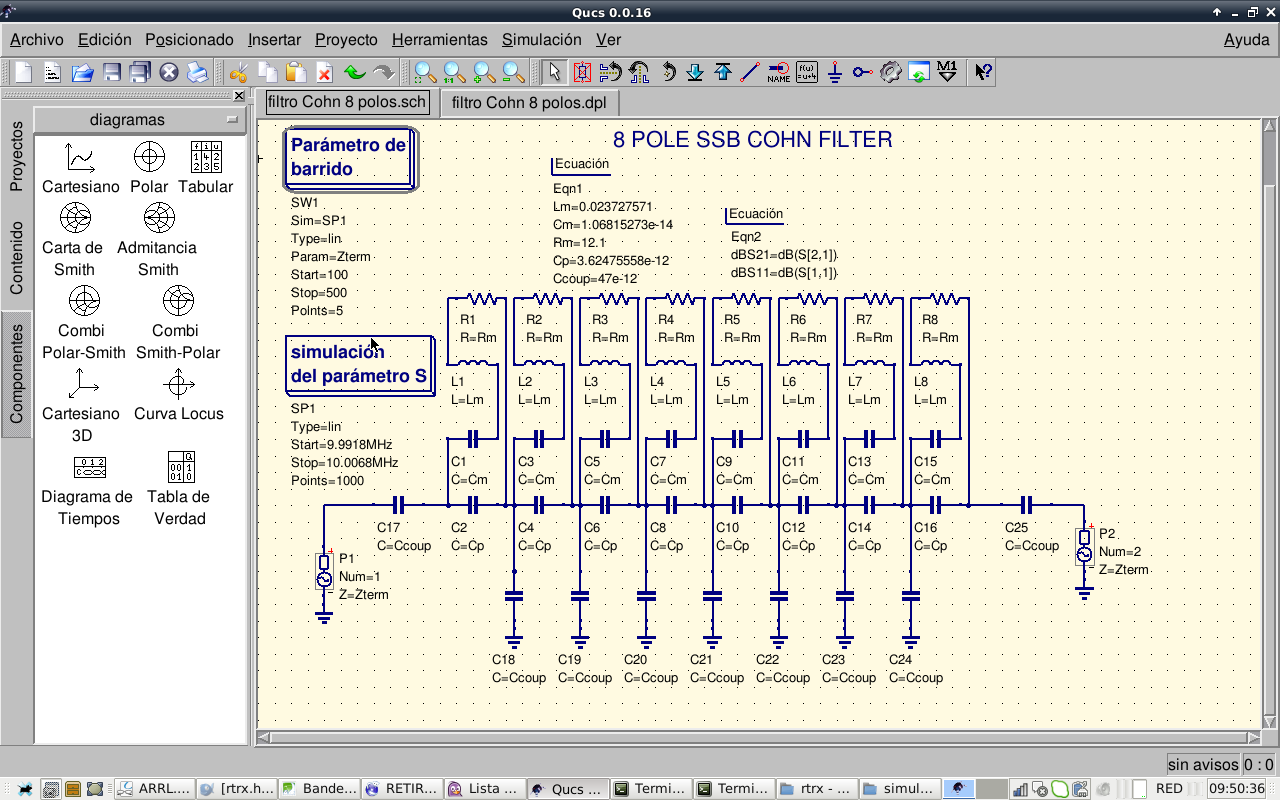
FIGURE24: SIMULATION SETUP USING QUCS SOFTWARE
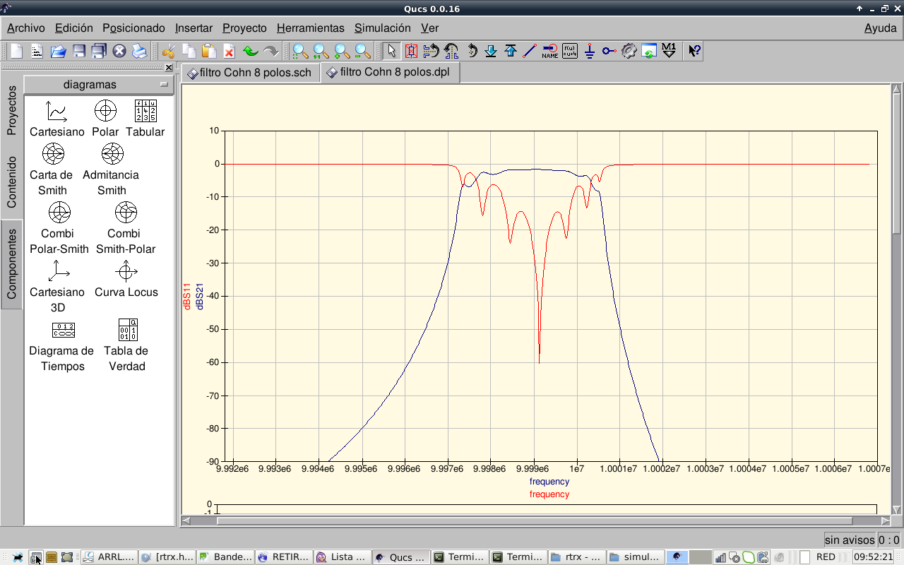
FIGURE25: S21 and S11 SIMULATION AT 340 OHM SYSTEM IMPEDANCE
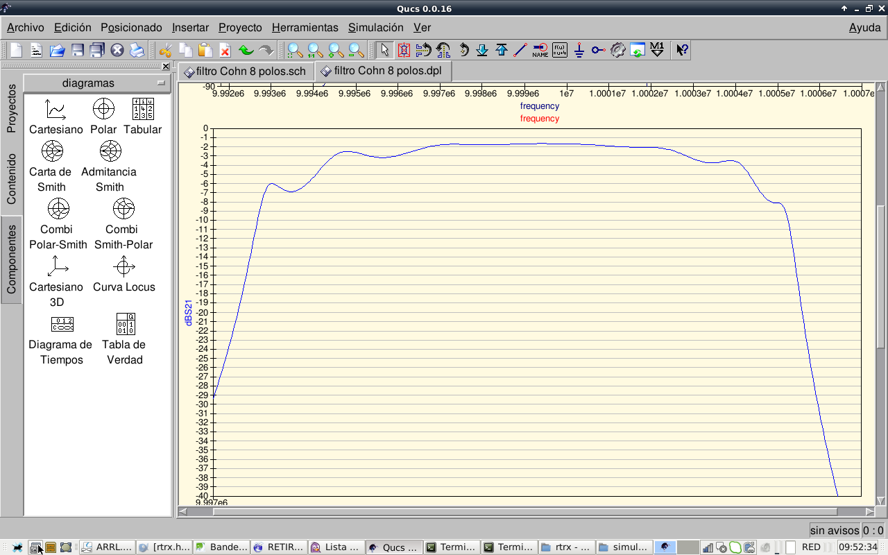
FIGURE26: FILTER PASSBAND CLOSEUP AT 340 OHM
Let's see if we can find a better impedance match, for that, I made an impedance sweep from 100 to 500 ohms in 100 ohm steps.
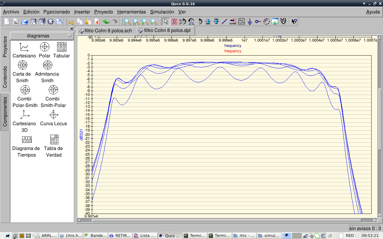
FIGURE27: FILTER PASSBAND CLOSEUP AT 100, 200, 300, 400 AND 500 OHM SYSTEM IMPEDANCE
To increase the differences, I made zoom in dB scale. It can be seen that a good shape is obtained between 300 and 400 ohms
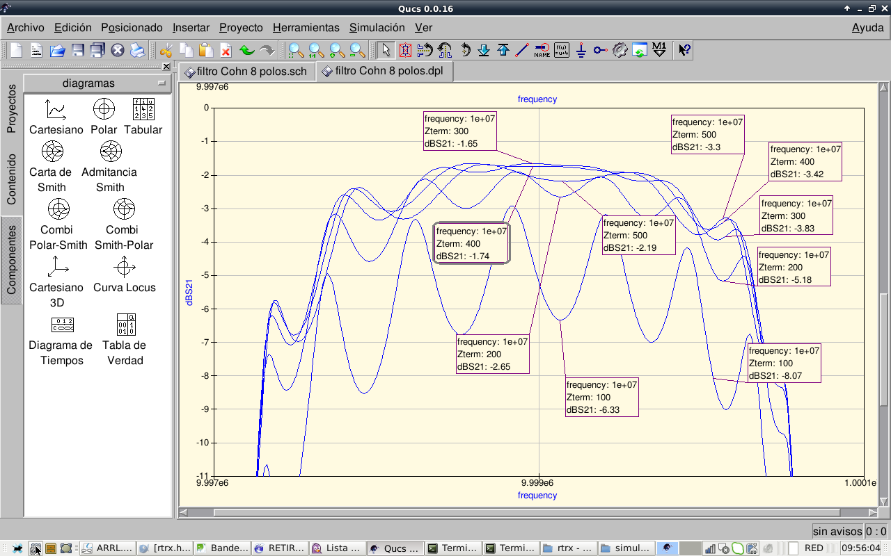
FIGURE28: FILTER PASSBAND AT 100, 200, 300, 400 AND 500 OHM SYSTEM IMPEDANCE. EXPANDED VIEW
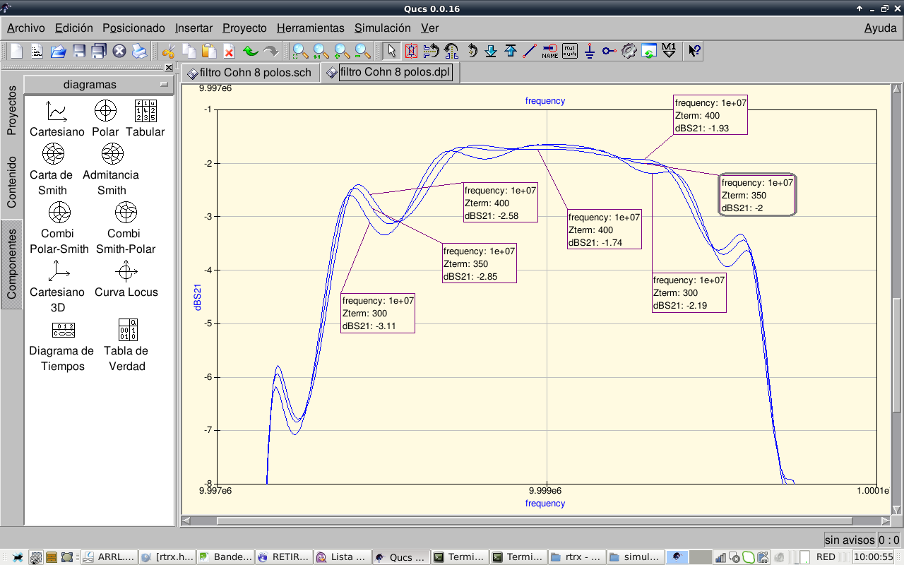
FIGURE29: FILTER PASSBAND AT 300, 350 AND 400 OHM SYSTEM IMPEDANCE. EXPANDED VIEW
350 ohms seems to be the good one. Any way, if we take a look like this, they are very similar, not critical at all:
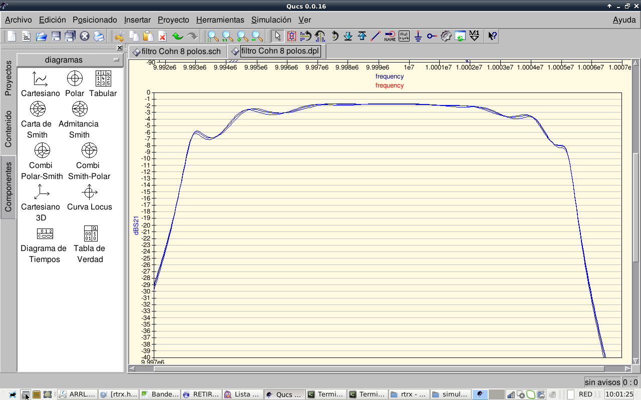
FIGURE30: FILTER PASSBAND AT 300, 350 AND 400 OHM SYSTEM IMPEDANCE.
The last experiment is taking into account the effect of crystal Q in filter passband. As we van see, the effect of Rm, lowering the Q, is smoothing filter shape and increase filter losses.
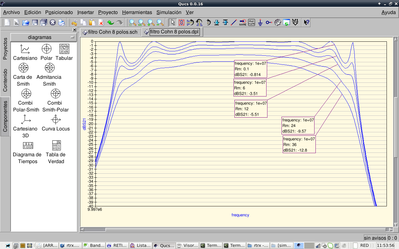
FIGURE31: EFFECT OF CRYSTAL Q.
So, after this experiments we conclude that the 8 pole Cohn filter cannot be improved further, it works as is. Other kinds of better passband shape filters like Chebychev will be investigated. Now I take a rest with filters.…this filter, as is now, should work reasonably well. I will continue with other receiver stages.
The CW filter
Same procedure was applied to get the CW filter. Selected crystals parameters are shown below:
| filter F spread (Hz) | # | f / Hz | Q | L / H | C / F | R / Ohm | C0 / F | figure of merit |
| 82 | 9997815 | 118834 | 0,023679 | 1,070210363E-14 | 12,52 | 3,638694106E-12 | 0,004570000 | |
| 62 | 9997814 | 125012 | 0,023464 | 1,080003084E-14 | 11,79 | 3,603570769E-12 | 0,004410000 | |
| 87 | 9997809 | 128303 | 0,023270 | 1,089000445E-14 | 11,39 | 3,724771612E-12 | 0,004590000 | |
| 43 | 9997797 | 131939 | 0,023596 | 1,073956779E-14 | 11,23 | 3,541775526E-12 | 0,004900000 | |
| 29 | 9997797 | 122483 | 0,022925 | 1,105431255E-14 | 11,76 | 3,643597629E-12 | 0,003240000 | |
| 23 | 9997793 | 129643 | 0,023280 | 1,088558636E-14 | 11,28 | 3,559792765E-12 | 0,004820000 | |
| 91 | 9997790 | 131921 | 0,023141 | 1,095093031E-14 | 11,02 | 3,647664596E-12 | 0,004140000 | |
| 30,1 | 13 | 9997785 | 146496 | 0,022997 | 1,101965638E-14 | 9,86 | 3,672506358E-12 | 0,004260000 |
| AVERAGE | 9997800 | 129329 | 0,023293958 | 1,0880274E-14 | 11,4 | 3,62904667E-12 |
A simulation was performed using average parameters and increasing the value of the coupling capacitors to reduce bandwidth. Filter impedance decreased until a 50 ohms match was obtained. Luckily the bandwith was addecuate for CW operation.
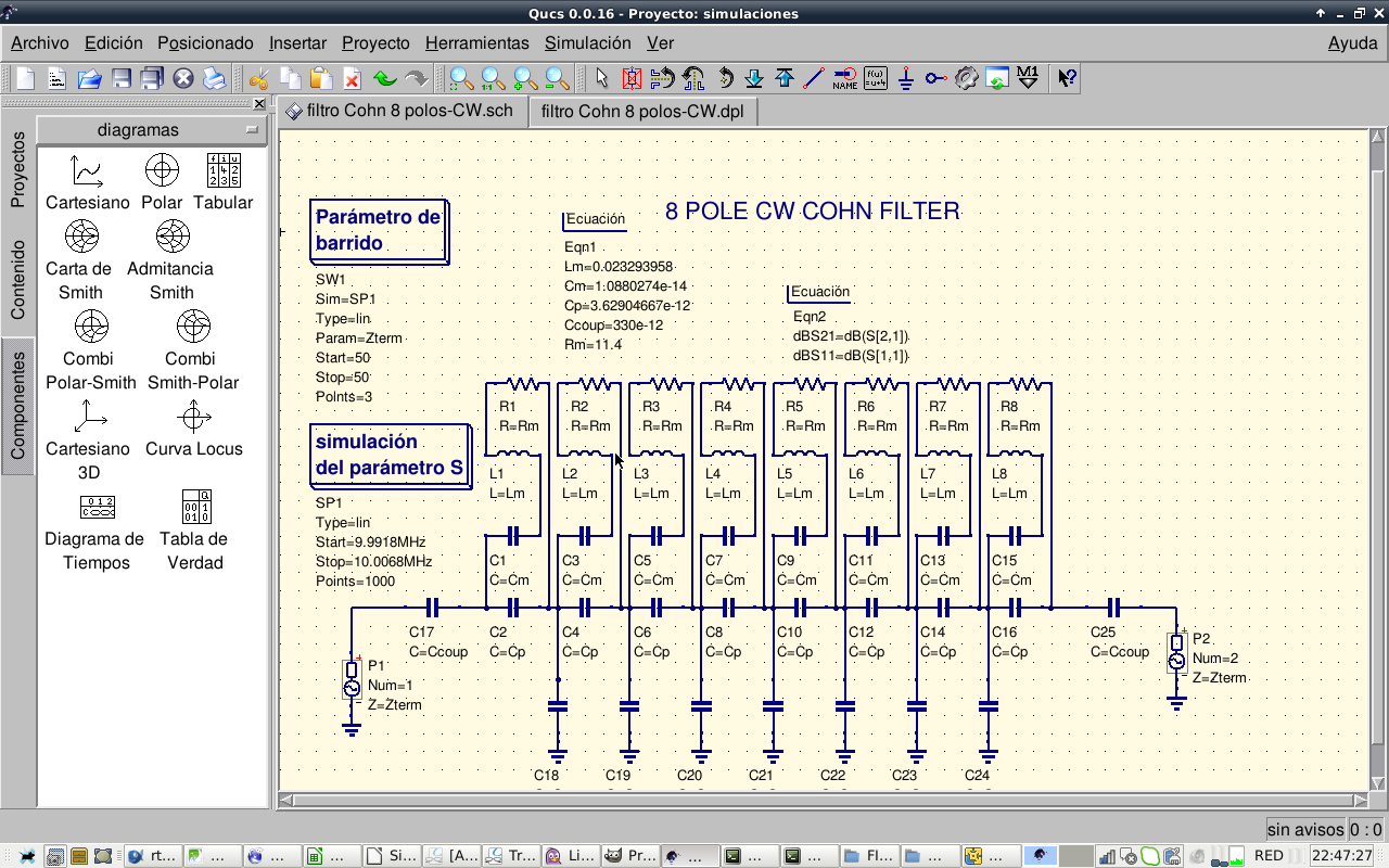
FIGURE32: CW COHN FILTER DESIGN
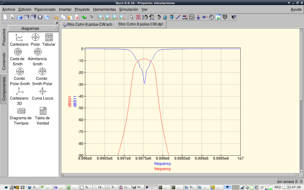
FIGURE33: CW COHN FILTER SIMULATION
A filter was built using the ugly construction method.
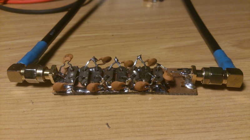
FIGURE34: CW COHN FILTER WITH GROUNDED CRYSTAL SHIELDS
Filter was measured using VNWA3 vector analyzer. Filter loss was high as expected:

FIGURE35: CW COHN FILTER -3dB BW
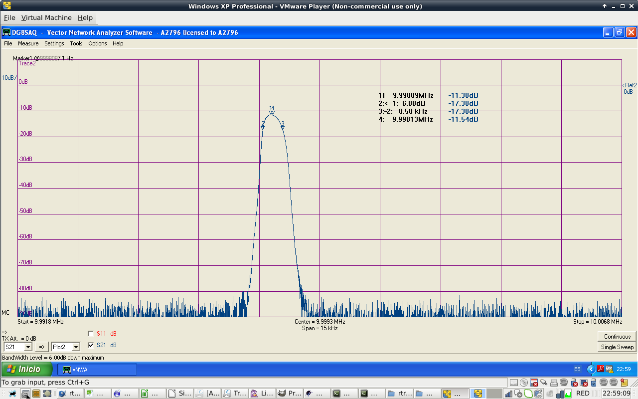
FIGURE36: CW COHN FILTER -6dB BW
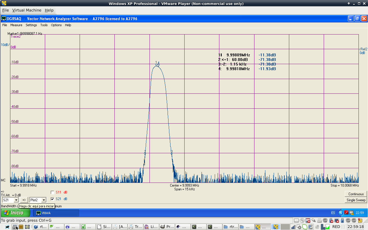
FIGURE37: CW COHN FILTER -60 dB BW
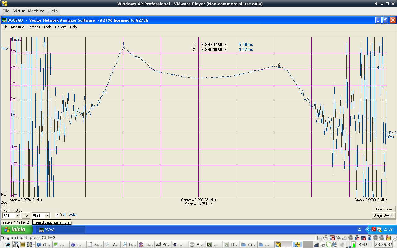
FIGURE38: CW COHN FILTER GROUP DELAY
400 Hz CW Cohn filter measured specifications (330pF coupling capacitors)
design -3dB BW: 400 Hz
poles: 8
design output impedance: 50 ohms.
design input impedance: 50 ohms.
passband center attenuation: -11.4 dB
Bandwidth: 390 Hz @ -3dB
Bandwidth: 500 Hz @ -6dB
Bandwidth: 1.15 kHz @ -60dB
Shape factor: 1150/500= 2.3    (-6dB/-60dB)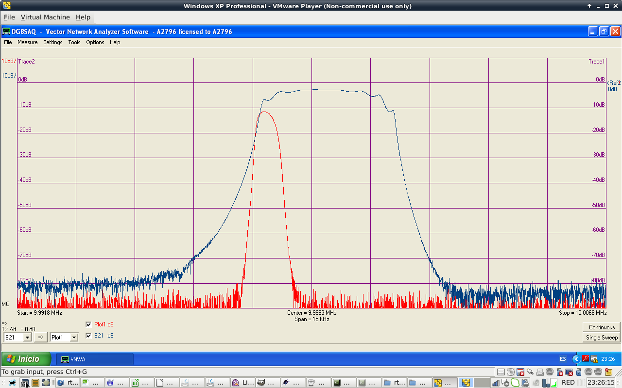
FIGURE39: CW VS SSB FILTER
That is the end of IF filter experimentation.
Bibliography
Experimental Methods In RF Design. ARRL. Wes Hayward, W7ZOI, Rick Campbell, KK7B, and Bob Larkin, W7PUA